FAQ
APM Offers services for Reverse engineering which includes 3d-Scanning, Surface Modeling and Solid Modeling. It also offers services for Quality Control and Inspection of complex free form parts.
- 1. 3D Scanning / White light Scanning
- 2. Surfacing
- 3. Solid Modelling
The process of Reverse Engineering can be broken up into following constitute parts
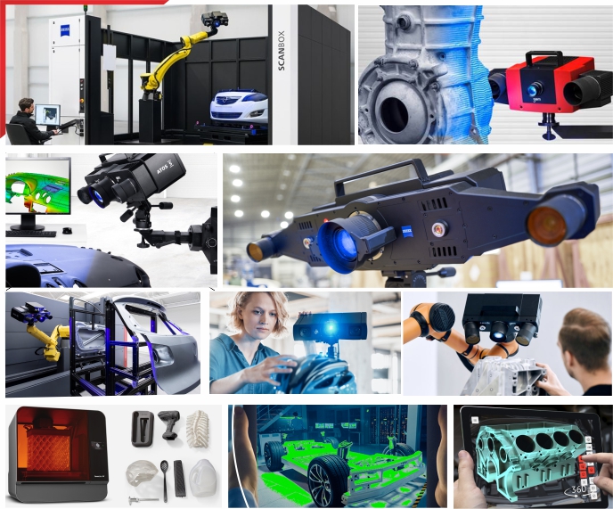
- APM uses Optical non - contact Blue light scanning system from M/s Gom GmbH, Germany for 3D-Scanning. This technology is currently considered the best in the field of 3d-scanning due to various advantages- Points are scanned on the surface of the part hence no complex compensation is required and so errors due to wrong compensation are avoided.
- A wide variety of parts and materials can be easily scanned including metal, wood, plastic, glass, epoxy, modeling clay, soft materials like foam, rubber etc
- A wide range of size can be accommodated on a Blue light scanner varying from 5mm to 10000mm ( yes it is 10000 mm or 10m )
- A very high density of point cloud data is generated
- The process is many times faster than conventional contact type methods.
- As part orientation can be changed during the process so scanning of all sides of the part can be done without expensive fixturing.
- It is possible to scan the inner details of parts like castings etc after cutting, without loosing the datum.
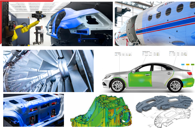
- There is no limitation on the job weight so heavy parts like dies and moulds, complete two wheelers and four wheelers can be easily scanned. The system is portable and can move to the site for scanning
Blue light scanning is a 3d-scanning process using a non-contact optical scanning device which uses blue light source to project fringes on the part being scanned. The sensor of the scanner which is equipped with two cameras take several ../images of the part ( with fringes projected on it ) during the measurement and sends these ../images to a high end PC where an advanced image software calculates point co-ordinates through out the visible area of the part under scan.
Unlike contact scanning, white light scanning picks up the point co-ordinates of the surface being scanned so there is no requirement for probe ball compensation and complexities / errors associated with it
Process - The Blue Light scanning systems projects fringe patterns on the component and the two cameras simultaneously capture ../images, then advanced software algorithms triangulate and calculate 3d-coordinates of numerous points spaced all over the surface of the part. The area of the part that is within the frame ( illuminated zone with fringes ) gets scan during a single measurement. For scanning complete part several such measurements are carried out and merged together with the help of markers fixed on the part. ATOS family is a two camera stereovision optical white light scanner which is considered best in its category &offers precise, reliable and accurate result. White Light Scanning is an optical 3D Scanning method preferred by most Industries for their 3D Scanning needs
Photogrammetry is a co-ordinate measuring technique to generate 3D-co-ordinates of points & features from a group of photographs taken from different points in space.
This science is being used for various applications ranging from generating maps from satellite or aerial photographs to calculate the precise 3D-co-ordinates of industrial parts ranging in size from a few mm to as large as 50 m (or more).
We restrict our description to measuring 3D-co-ordinates of points on industrial parts.
Process- Pictures are taken by a high resolution digital camera from different view points and sent to a computer via physical connection or wireless connection. Intelligent software collates all the pictures and does a bundle analysis to calculate 3D co-ordinates of marked points.
Why is photogrammetry required ? Can we scan without photogrammetry ? In order to get a better accuracy in scanning process we do photogrammetry. The concept of photogrammetry is to precisely calculate the coordinate of the non-coded marker all over the object in one go.
This enhances the accuracy of merging of scan output from multiple shots specially when scanning a large part like a complete car or aircraft.
Although it is not mandatory to do photogrammetry prior to scanning but for large objects the accuracy improves is significant and hence preferred
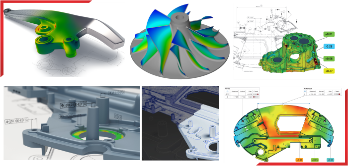
The output of scanning is a dense copious point cloud & tessellated or triangulated stl file ordered sections parallel to principal planes or user defined planes can be extracted from the point cloud data. This Output can be exported in IGES, VDA, ASCII or STL format
Yes it is possible to do machining on point cloud for some application like wood pattern machining, roughing etc. However machining for moulds, dies etc. will need an intermediate process of Surface & Solid modeling on point cloud.
We can give surface/Solid model in native formats of UG, Ideas or Pro-engineer we can also give the output is neutral formats i.e. IGES, Step, VDA, Parasolid etc
Surfacing is a process of fitting surface entity in a cloud of points ensuring specified geometric tolerances. Surfacing is required in order to use the scan data for machining smooth surfaces mainly for die/mould production, analysis, digital mockups or packaging purposes.
In case you haven't found the answer for your question please feel free to contact us, our customer support will be happy to help you.